This page describes a very simple electronic fuel cut defender circuit you can use to eliminate the overboost protection present in many stock engine computers. I have a Subaru Legacy Turbo, so it's got an EJ22T slant, but the same basic idea would work on many cars.
The way most ECU overboost protection works is by monitoring manifold pressure through a pressure sensor. When the readings go too high, the ECU stops pulsing the fuel injectors. On the Legacy Turbo, this happens when the ECU reads a pressure above approximately 28 psia for longer than approximately 3 seconds.
The pressure sensor generally outputs a voltage linearly related to pressure as long as pressure remains within its valid range. The Subaru pressure sensor can read up to approximately 29 psia. The output voltage more or less follows this relationship:
Where Vout and Vref are in volts and P is in psia. Vref is supplied by the ECU and is approximately 5 volts.
So, if we can ensure the ECU never sees a reading above around 4.3 volts, we can eliminate the fuel cut. Here's one way:
The basic idea behind this circuit is this:
All three op amps are acting as unit-gain buffers which take their feedback from the circuit's output.
The op amp to the right is simply a voltage follower to ensure output impedance is low.
The upper op amp tries to drive the output signal to equal the input but its output impedance is limited by the resistor.
The lower op amp tries to drive the input to equal a reference voltage defined by the voltage divider (this would ideally be just below the fuel cut voltage). It has a low output impedance but, because of the diode, can only pull the output towards the negative rail.
The result is that when the input is below the voltage defined by the divider, the output follows the input. When the input is above this threshold, the output follows that threshold.
A practical realization of this circuit as applied to an EJ22T looks something like this:
+12v would go to an ignition-switched 12-volt source. +5v would tap into the sensor's reference voltage line. Input would come from the sensor, and output would go to the ECU.
The 10K and 47K resistor set the clamping voltage at approximately 27 psia.
The "+5v" line should be spliced into the ECU's MAP sensor power supply pin. The "+12v" line should be spliced into the ECU's MAF sensor power supply pin. The "ground" line should be spliced into the ECU's MAP sensor ground pin. Finally, the ECU's MAP sensor signal wire should be cut. The sensor side should be connected to the "input" line and the ECU side to the "output" line. Done this way, you only need to mess with one of the ECU's four connectors.
For information on EJ22T ECU pinouts, look here: http://www.surrealmirage.com/vrg3/ecupins/
The LM224 is a tougher version of the more common LM324. The LM324 is only rated for operation at temperatures between 0 and 70 degrees Celsius, while the LM224 is rated for -25 to +85 degrees Celsius. If you really want to just use parts your local Radio Shack carries, you could probably get away with an LM324, but you technically might take it out of the manufacturer's specified operating conditions when you use it in a car.
If you want to eliminate the need for the +12v power supply, you could use a TLV2374 op amp instead. The TLV2374 has rail-to-rail inputs and outputs, so you could just connect pin 4 to the +5v source instead of +12v.
I drew the above diagram in such a way that it would be really easy to transfer to Radio Shack's general-purpose IC printed circuit board (part number 276-159):
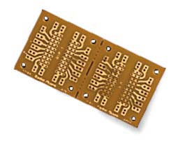
After cutting away unused portions of the PC board, it'd look something like this:
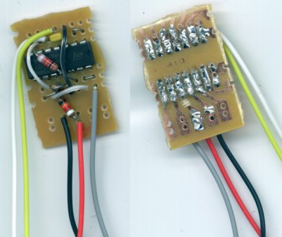
You could also build it free-standing without a circuit board:
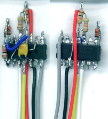
You could then seal it with epoxy for a very rugged package that could probably even stand being in the engine bay (though it's still probably best installed next to the ECU).
If you went to Radio Shack and bought all the stuff (substituting an LM324 for the LM224 of course) it'd probably cost about $10. Some careful shopping would cut that price down closer to $2.
If you wanted to make the circuit adjustable (so you could use it on a variety of cars), you'd just need to replace the fixed voltage divider with a potentiometer. A trimpot would be sensible. To increase the resolution of the adjustment, it would make sense to limit its adjustability to the upper half of the voltage range, since I would imagine no factory engine management system would waste 50% of the sensor's resolution:
The design on this page is a revision of my original design. This version reduces the effect of input offset voltage. For posterity's sake, the original writeup is here: original_design/.
Warning: This type of FCD eliminates the factory overboost prevention, which is an important engine protection device. Should a vacuum hose come loose, or something else go wrong, the turbocharger would be permitted to boost as much as physically possible, potentially causing untold amounts of engine damage. It would be wise to incorporate another form of overboost protection when using a circuit like this one. Also, the ECU will be unaware of the increased boost levels, which may interfere with its fuel and/or ignition control. And if the ECU in your car fuels based on the pressure sensor readings (if it's a "speed density" system), this FCD will certainly prevent proper fueling, and something will need to be done about that.